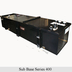
Series 400
For applications requiring a tank up to 64"W x 167"L x 36"H
The Series 400 sub base design was developed by Tramont for applications requiring a tank up to 64"W x 167"L x 36"H. By making some design modifications to Series 700, Tramont was able to reduce the dollar cost-per-gallon, while offering additional standard features such as removable end channel for access to the electrical stub up. Series 400 also weighs less, offering potential savings on freight. Series 400 is available in single wall (primary), closed top diked and secondary containment. These styles also are available as day tank sub bases. Series 400 is not offered in open top diked style.
Standard Features
- Removable end channel for access to the electrical stub up
Construction
- Built and tested in accordance with Underwriters Laboratories and NFPA standards
- UL-142 Listed
- Constructed in accordance with
- Flammable & Combustible Liquids Code, NFPA 30
- The Standard for Installation and use of Stationary Combustible Engine & Gas Turbines, NFPA 37
- The Standard for Emergency and Standby Power Systems, NFPA 110
- Rectangular - including reinforced steel box channel for generator support, with load rating of 5,000 lbs. per gen set mounting hole location
- Pressure washed with an iron phosphate solution
- Interior is coated with a solvent-based film rust preventative, providing inter-operational protection
Testing
- Primary Tank and Secondary Containment Basin are pressurized at 3-5 psi and leak- checked to ensure integrity of sub base weld seams per UL-142 standards
- Closed Top Dike Primary tank sections are pressurized at 3-5 psi and leak checked to ensure integrity of sub base weld seams per UL-142 standards. Containment basin is leak checked by weld penetrant and ultraviolet light.
Fittings
- Appropriately sized NPT fuel supply
- Fuel return fitting
- 2" NPT for normal vent
- NPT for emergency vent, size as appropriate
- 2" NPT for manual fill
- NPT for level gauge, sized as appropriate
- 3/8" NPT basin drain (tank drain if single wall)
- 2" NPT for level alarm
- NPT fitting for leak detection alarm
Fuel Level Gauge
- The sub base tank shall include a direct-reading fuel level gauge
Fuel Containment Basin
- Sub base tanks include a welded steel containment basin, sized at a minimum of 110% of the tank capacity to prevent escape of fuel into the environment in the event of a tank rupture
Leak Detection System
- Sub base tanks come with a fuel containment basin leak detector switch
Venting
- Normal Venting
- Sized at 2" NPT through 10,000 gallons in accordance with The American Petroleum Institute Standard No. 2000, for venting atmospheric and low pressure storage tanks
- Atmospheric (normal) vent cap with screen provided
- Emergency Venting
- Sized to accommodate the total capacity of both normal and emergency vents, and is not less than that derived from NFPA 30, Table 2-8, based on wetted surface area of the tank (calculated based on 100% of primary tank)
- Zinc-plated emergency pressure relief vent cap
- Vent is spring-pressure operated
- Opening pressure is 0.5 psig
- Full opening pressure is 2.5 psig
- Limits marked on top of each vent
- Second emergency vent fitting is provided for the secondary containment portion of the tank, if applicable.
- Electrical
- Immersion heater
- Mechanical
- Venting
- Emergency pressure relief venting
- Sub base vent/fill/alarm packages for dual wall secondary containment generator base tanks
- Shipping skids and wrapping
- Local approvals


